1.Simulator Internal
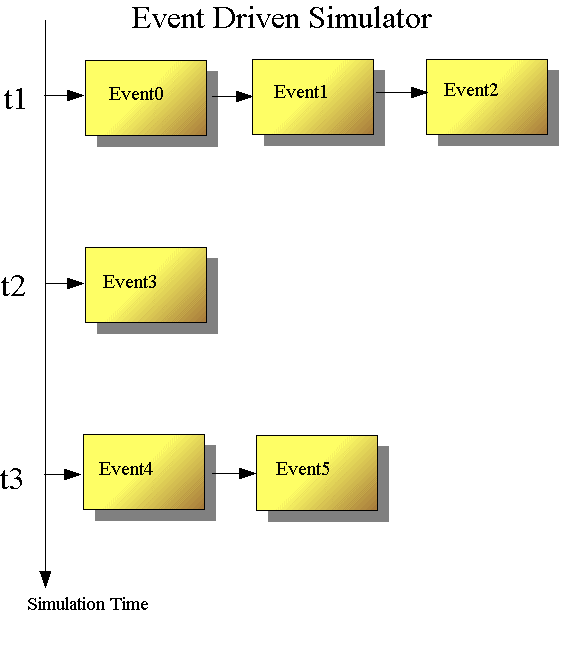
The Verilog HDL is defined in terms of a discrete event execution model.

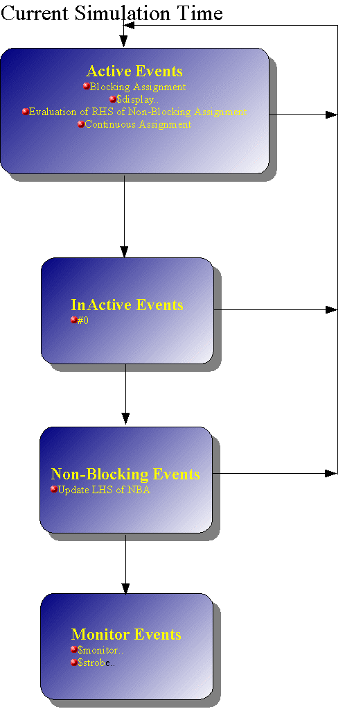
The order at the current simulation time is divided as 4 regions.

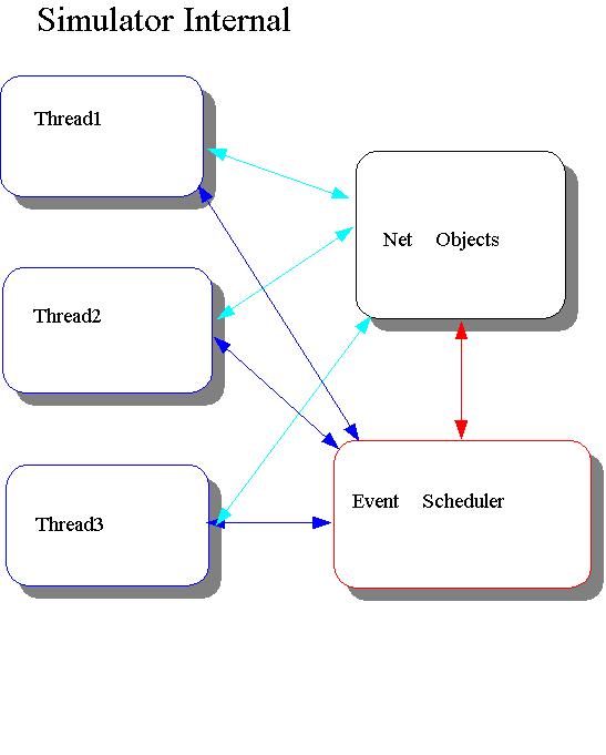
In Simulator perspective, Internal structure will be as follows.
Each process(initial/always behavior codes) will be processed at each
thread. Net-Objects(gates) are something like actual circuit component,
and event scheduler handles event scheduling.

1.1 Verilog Race Condition
Verilog evaluation order is rather difficult to understand.
Let's look at a sample source for current time.
The problem here is how your simulator will display.
//Mar.20.2004
//Demo for verilog race condition
module sample5;
        reg q;
        wire p;

assign p = ~q;
initial begin
q = 1;
q <=0;
$display ("p=%b q=%b",p,q);//
#0
$display ("p=%b q=%b",p,q);//p should be 0
$strobe ("p=%b q=%b",p,q);//Absolutely  p should be 1
end

endmodule
Veritak and most simulators should display as follows.
p=x q=1
p=0 q=1
p=1 q=0
p=x depends on implementation of simulator. LRM allows both p=0 and p=x.However,bold
characters should be the same result as above, independent of simulator.
Let's look at more in detail
First statement q=1; causes propagate event to assign p=~q; The problem
is calculation of propagate event first, or $display first. If simulator
calculate the assign statement prior to $display, p=should be
0. Since both are active events, nondeterminism is due to LRM
that active events can be taken off the queue and processed in any order.
However most simulators answer should be p=x.This is to minimize overhead
from switching engines, it will evaluate gates until there are no more
events there for the current time, then evaluate behavioral code until
there are no more events there for the current time, back and forth.
Let's look at $display after #0. This was inactive events. It should be noted this statement should not be processed until there are no more active events (including assign event p=~q); Therefore it should result p=0 q=1.
Non-Blocking assignment will be processed at region 3 after region
2 (inactive event) in figure above. This cause p=1 q=0.
$strobe/$monitor guarantees the final value at current simulation time
at region 4.