7.1 How UART works ?
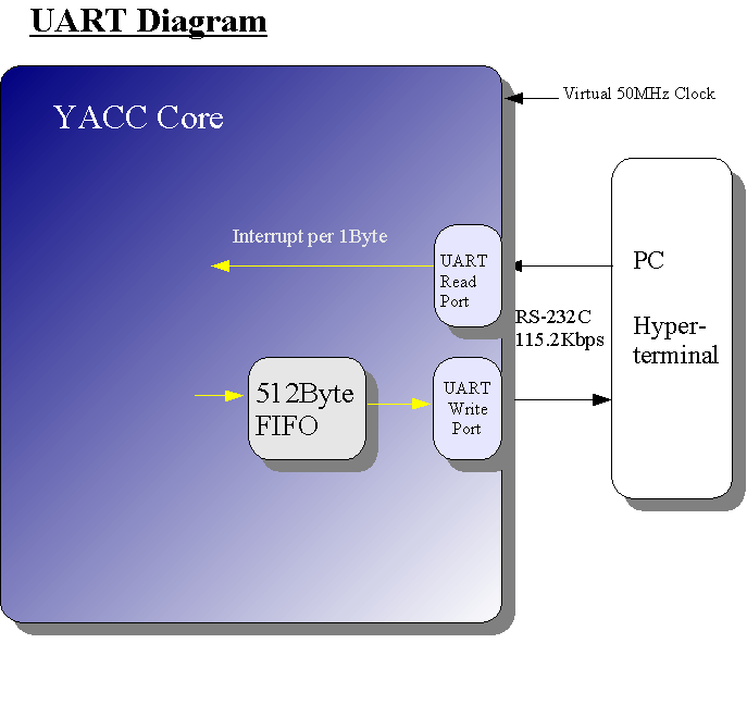
YACC has Write/Read port of UART.
Sending Data to PC is queued by 512Byte FIFO. In normal situation, YACC can do another job while
UART is processing. data. UART Read port generates interrupt to YACC per 1Byte data. There is no FIFIO for read port since 1Byte time is
fully enough to detect interrupt and process the 1Byte read data from UART
port for YACC.
Example
Let's see an example.
First we make program for UART testing.
To process the memory initialization file,
Go to the folder "bench/c_src/calculator".
do "complie.bat".
This batch file will generate the program and transfer it
to the folder where RAM in RTL will read.
Here is a C source.
At first, Send "5*3" to TX port , and then "100*31"
and then "-31050*-31"..very simple program.
Since Write Port has 512Byte FIFO, program will proceed "label:" immediately, where is endless loop.
void main()
{
        unsigned counter=0;


        set_interrupt_address();//Set Interrupt Service Address

    print_uart("5*3\n");//Send UART PORT TXD, then echo backed to RXD in verilog test bench.
        print_uart("100*31\n");//Don't care overflow,Altera Imprementation has UART FIFO 512bytes
        print_uart("(-31050)/(-31)\n");
        print_uart("(-1053333)/(231)\n");
    print_uart("(10503)/(-314)\n");
    print_uart("3333*3333\n");
        print_uart("533*443\n");
        print_uart("10*314\n");
        print_uart("(-350)/(-231)\n");
        print_uart("(-10533333)/(1231)\n");
    print_uart("(105034)/(-3134)\n");
    print_uart("3363*33333\n");
        label:
        if (int_flag){//if interrupt service routine reports end of string,
                        int_flag=0;
                        calculator();//then parse the string,calculates, and report the result to debug port.
                        counter++;
                        if (counter>=12)        print("$finish");
        }
        goto label;

}
void calculator()
{
        long result;

//Parser Initialization
        init_parser();

//Calculation
        result=expression();

//
        #ifdef DEBUG
        print("\n");
        print(buffer);
        print("=");
        print_long(result);
        print("[Hex]   ");
        itoa(result,result_buffer);
        print(result_buffer);
        print("[Dec]\n");

        #else
        print_uart(buffer);
        putc_uart('=');
        print_uart(result_buffer);
        putc_uart(0x0a);
        putc_uart(0x0a);
        putc_uart(0x0d);

        #endif


}
Let's simulated in RTL.
Load Veritak Project "generic_ram_rtl_calculator_test_using_uart_echo_w_save.vtakpr".
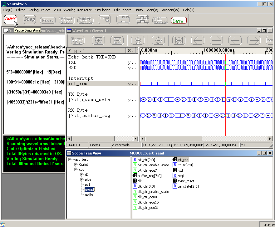
It takes much time to complete the project..So press "Pause"
button as below.
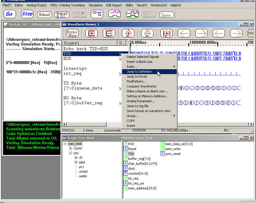
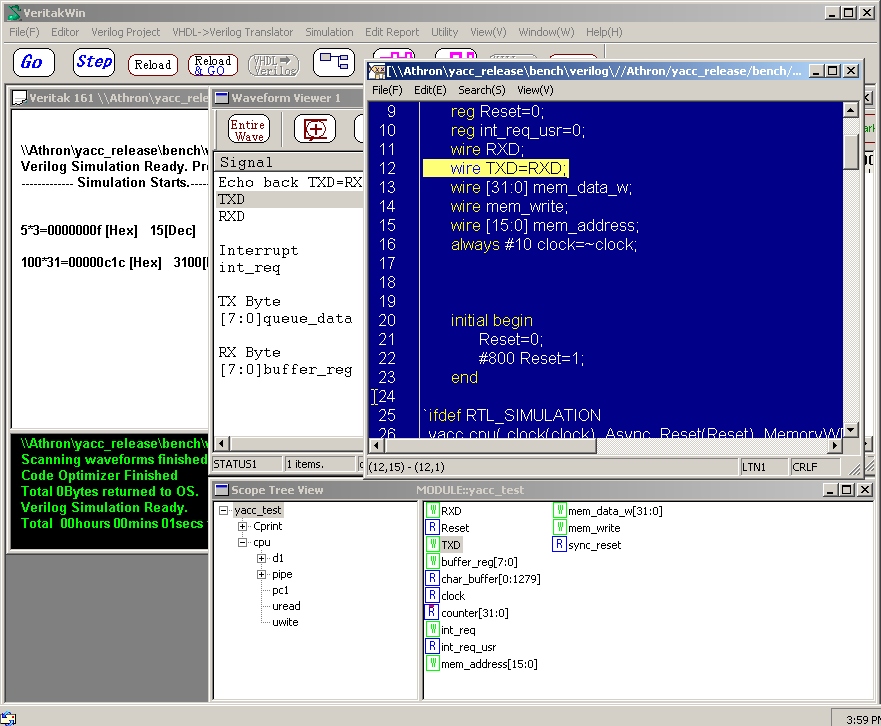
It this project TX is echo-bakced to RX. You can go to source where TX is connected to RX, as shown in below.
In waveformview below, RX receives the data that TX sends. We can see 5*3
100*31 (-310530)/(-31) in both TX and RX Byte.
"Int_req" is generated interrupt request to YACC from UART read
port. The term is 1Byte time, around 91.8us.
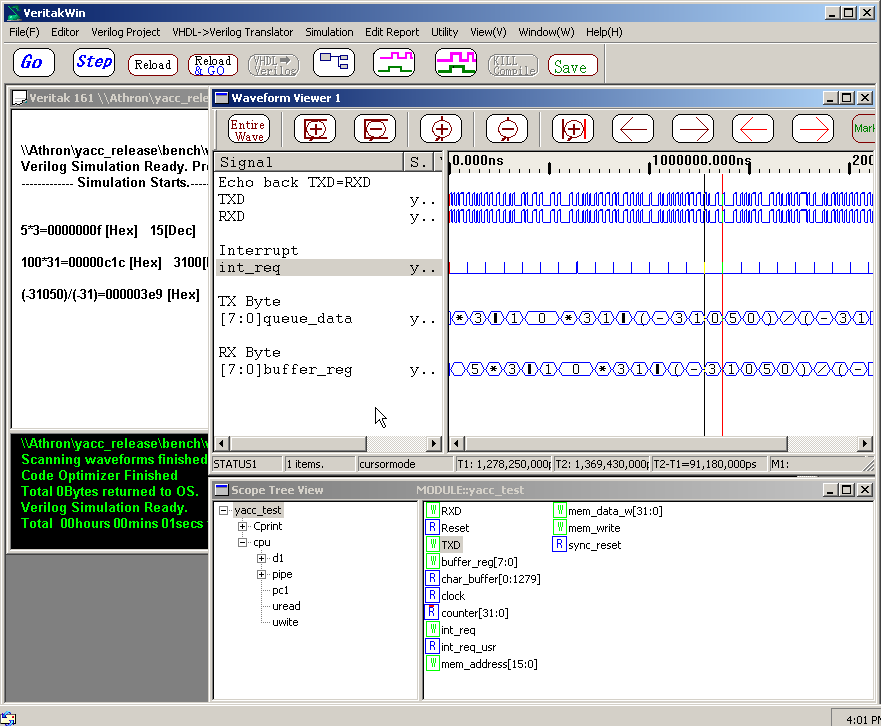
C routine "calculator" calculate received stream "5*3...",
( In RTL simulation "DEBUG" is asserted.)
and write the result via debug-port, which are displayed in console on
simulator.
"Cprint" task in Top of test will do this work.
That's how I confirmed H/W ( RX /TX port and interrupt logic)
and software (C program) worked well in RTL simulation.
H/W configuration is described in "define.h".
Change hardware property as your like.