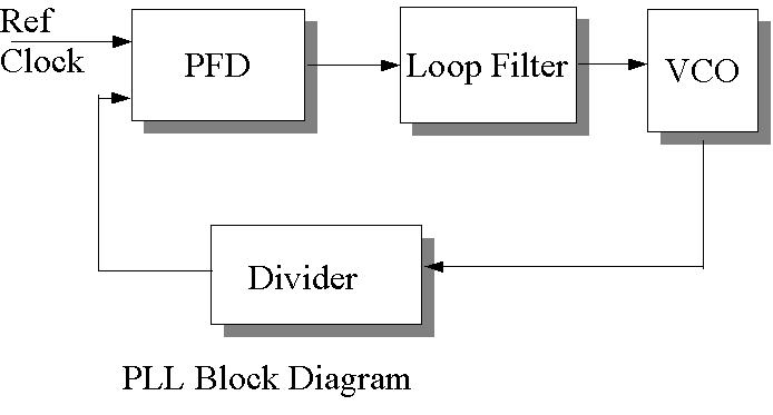
1. Block Diagram
Analog PLL Design and Simulation by Verilog HDL
1. Block Diagram
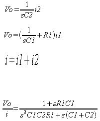
2. Transfer Function
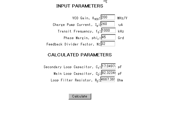
3. Web-Calculator
To calculate appropriate constant C1/C2/R1, following web-calculator is
convenient.
http://geocities.com/fudinggepll/pllfilterprogram.html
In the site you can get value of C1/C2/R2 as follows.
4. Transfer Function to State Space Model
Since Veritak needs state-space model, following script (MATLAB) is used.
C2=17e-12
C1=82e-12
R1=4667
R1C1=R1*C1;
C1_C2=C1+C2;
C1C2R1=C1*C2*R1;
b=[R1C1 1];
a=[C1C2R1 C1_C2 0];
[A,B,C,D] = tf2ss(b,a)
a2=[C1C2R1 C1_C2 0 0];
kv=200e6;
ki=260e-6;
N=32;
Gain=kv*ki/N;
W=logspace(4,9);
freqs(b*Gain,a2,W)
save 'F:\verilog\PLL\loop_filter.txt' A B C D -ascii -double
In comparison, let's try additional two cases, less phase margin of 15degree
and much phase margin 75degree.
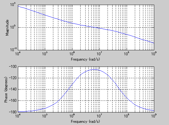
Open-loop frequency response will be as follows.
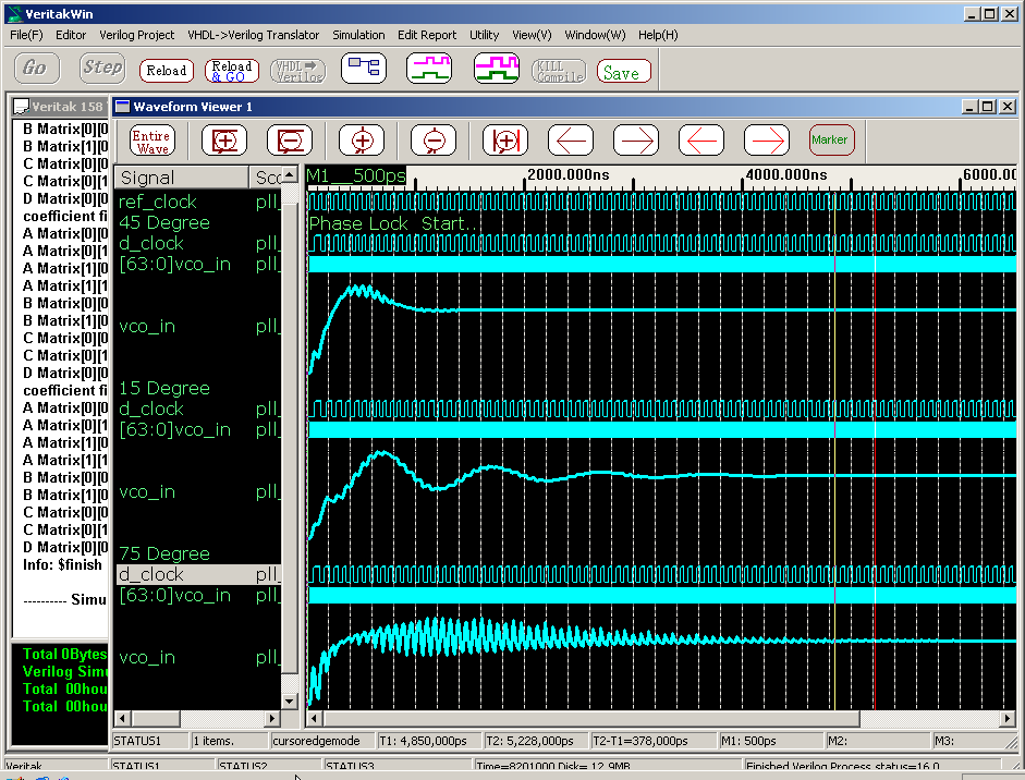
Degree 45
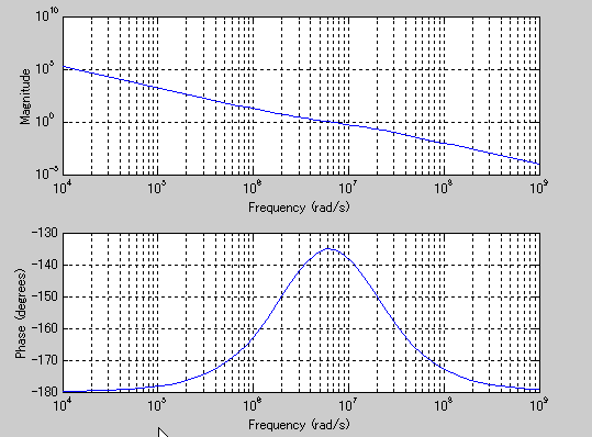
Degree 15
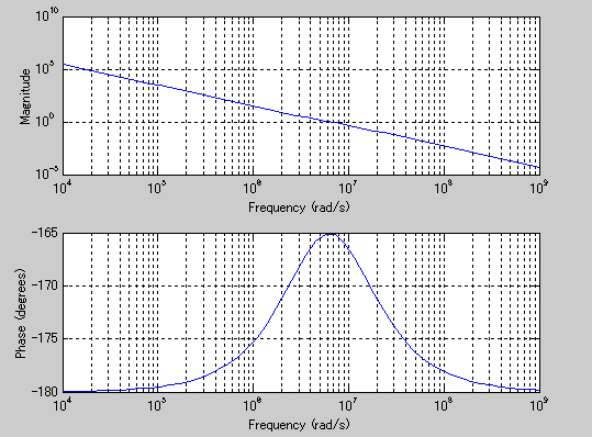
Degree 75
5. Analog Simulation
Here is a source code written by Verilog-2001
//May.6.2005
//Analog PLL demo
`define CYCLE (1.0/13.56/2*1e6 )
`timescale 1ps/1ps

module pll_test;
        reg ref_clock=0;

        always #(`CYCLE) ref_clock=~ref_clock;


pll_module #(.File_Name("loop_filter.txt")) PLLl_1MHz (ref_clock);
pll_module #(.File_Name("loop_filter1MHz_much_phase.txt")) PLLl_1M_Much(ref_clock);
pll_module #(.File_Name("loop_filter1MHz_less_phase.txt")) PLLl_1M_Less(ref_clock);


endmodule

module pll_module #(parameter File_Name="loop_filter.txt") (input ref_clock);
        wire v_clock,d_clock;
        wire [1:0] iout;

        pfd pll1(.ref_clock(ref_clock),
                         .d_clock(d_clock),
                         .iout(iout));
        loop_filter_and_vco  #(.File_Name(File_Name)) lvco(.iout(iout),.v_clock(v_clock));
        divider #(.DRatio(16)) div(.v_clock(v_clock),.d_clock(d_clock));

endmodule

module divider  #(parameter integer DRatio=32)
                           (    input v_clock,
                                output reg d_clock=0);

                integer counter=0;

                always @(posedge v_clock) begin
                        if (counter==DRatio-1) counter <=0;
                        else counter <=counter+1;
                end

                always @(posedge v_clock) begin
                        if (counter ==DRatio-1) d_clock<=~d_clock;
                end

endmodule

module  loop_filter_and_vco #(parameter File_Name="loop_filter.txt")
                                                 ( input signed [1:0] iout,
                                                   output  v_clock);

        localparam real Igain=-(-260e-6);//A
        localparam real Igminus=260e-6;
        localparam integer cycle=100;//ps
        localparam real Vco_Gain=200*1e6;//Hz/V
        localparam real Center_Frequency=200e6;//433.92e6;//Hz

        real I;
        real read_array[0:10];// Input vector for rungekutta
        real write_array[0:10];//Output vector from rugekutta
        real vco_in;
        real omega,delta_theta;
        real theta,delta_theta;
        real vco_waveform;

        always @(*) I=Igain*iout;


        always #(cycle) begin

              read_array[0]=I;//
              $runge_kutta(File_Name,1);//Loop Filter V/I
                vco_in=write_array[0];//Get Loop Filter voltage
                omega=2.0*(Center_Frequency+vco_in*Vco_Gain)*$M_PI;
                delta_theta=cycle*1e-12*omega;//
                theta=theta+delta_theta;
                vco_waveform=$sin(theta);//
        end

        assign v_clock=vco_waveform>=0 ? 1:0;

        initial begin

                $runge_kutta(File_Name,0,read_array,write_array);//rugekutta Initialization
                #(8200*1000) $finish;
        end

endmodule

module pfd( input ref_clock,
                        input d_clock,
                        output reg signed [1:0] iout);

        integer state=0;
                always @(posedge ref_clock) state=state+1;
                always @(posedge d_clock) state=state-1;

                always @(*) begin
                                if (state>0) state=1;
                                else if (state<0) state=-1;

                                if (state>0) iout=1;
                                else if (state<0) iout=-1;
                                else    iout=0;

                end


endmodule
In control theory, 45 degree of phase margin is ideal for
proper settling time. That is confirmed in analog simulation by verilog-HDL.